
Developer's Corner
X-keys Button Panel (SE+MWII Firmware) Data Report
General Information
MWII |
SE |
|
VID |
05f3h |
05f3h |
PID |
02B9h or 697 |
0304h or 772 |
Consumer Usage Page |
1 |
1 |
Usage Page |
000Ch or 12 |
000Ch or 12 |
Button Panel Input Report
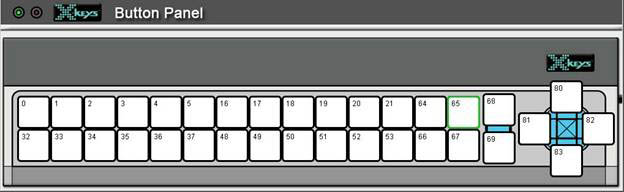
Figure 1: X-keys Button Panel key reference
Endpoint: 1, consumer usage page
MWII Report Length: 32 bytes.
SE Report Length: 19 bytes.
The following types of input reports are available; General Incoming Data and Check Key (MWII only). Const stands for Constant.
1. General Incoming Data. This is received when switches are pressed, unit ID changes, Program Switch changes position.
|
Byte 1
|
Byte 2
|
Byte 3
|
Byte 4
|
Byte 5
|
Byte 6
|
Byte 7
|
Bytes 8-17
|
Byte 18
|
Byte 19
|
Bytes 20-32
|
|
|
MWII
|
Const
|
Keys 0-6
|
Keys 16-21
|
Keys 32-37
|
Keys 48-53
|
Keys 64-69
|
Keys 80-83
|
Reserved
|
Unit ID (0-255)
|
Program |
Reserved
|
|
MWII
|
2
|
D1
|
D2
|
D3
|
D4
|
D5
|
D6
|
0
|
<data>
|
Swpos
|
value
|
|
SE
|
Const
|
Keys 0-6
|
Keys 16-21
|
Keys 32-37
|
Keys 48-53
|
Keys 64-69
|
Keys 80-83
|
Reserved
|
Unit ID (0-255)
|
Program |
NA
|
|
SE
|
0
|
D1
|
D2
|
D3
|
D4
|
D5
|
D6
|
0
|
<data>
|
Swpos
|
NA
|
D1: for all bits 0 for key up, 1 for key down. Bit
1=Key 0, Bit 2=Key 1, Bit 3=Key 2, Bit 4=Key 3, Bit 5=Key 4, Bit 6=Key 5,
Bits 7-8=0 always.
D2: for all bits 0 for key up, 1 for key down. Bit
1=Key 16, Bit 2=Key 17, Bit 3=Key 18, Bit 4=Key 19, Bit 5=Key 20, Bit 6=Key
21, Bits 7-8=0 always.
D3: for all bits 0 for key up, 1 for key down. Bit
1=Key 32, Bit 2=Key 33, Bit 3=Key 34, Bit 4=Key 35, Bit 5=Key 36, Bit 6=Key
37, Bits 7-8=0 always.
D4: for all bits 0 for key up, 1 for key down. Bit
1=Key 48, Bit 2=Key 49, Bit 3=Key 50, Bit 4=Key 51, Bit 5=Key 52, Bit 6=Key
53, Bits 7-8=0 always.
D5: for all bits 0 for key up, 1 for key down. Bit
1=Key 64, Bit 2=Key 65, Bit 3=Key 66, Bit 4=Key 67, Bit 5=Key 68, Bit 6=Key
69, Bits 7-8=0 always.
D6: for all bits 0 for key up, 1 for key down. Bit
1=Key 80, Bit 2=Key 81, Bit 3=Key 82, Bit 4=Key 83, Bits 5-8=0 always.
Swpos: Bits 1-3=0, bit 4=1, bit 5=0 if program
switch is down, 1 if program switch is up, bits 6-8=0.
Button Panel Output Reports
The following types of output reports are available; Set LEDs, Set Unit ID, Set Key (MWII only) and Check Key (MWII only). The Unit ID is a value between 0 and 255 which can be set and read. This number stays permanently in the device independent of computer. It is useful if more than one device of the same PID will be connected to the same computer in order to distinguish the devices uniquely. The Set Key and Check Key reports are for the dongle feature available on the Pendant and Button Panel, non PC users please contact P. I. Engineering for further details.
Endpoint: 2, vendor defined usage page
MWII Report Length: 8 bytes.
SE Report Length: 9 bytes.
1. Set LEDs
|
Byte 1 |
Byte 2 |
Byte 3 |
Byte 4 |
Byte 5 |
Byte 6 |
Byte 7 |
Byte 8 |
Byte 9 |
|
|
MWII |
Constant |
LED Command |
Constant |
Constant |
Constant |
Constant |
Constant |
LED Control |
NA |
|
MWII |
2 |
186 |
0 |
0 |
0 |
0 |
0 |
LED |
NA |
|
SE |
Constant |
Constant |
Constant |
Constant |
Constant |
Constant |
Constant |
Constant |
LED Control |
|
SE |
0 |
0 |
0 |
0 |
0 |
0 |
0 |
0 |
LED |
LED: Bits 1-6=0, bit 7=1 to turn on green LED or 0 to turn off green LED, bit 8=1 to turn on red LED or 0 to turn off red LED.
2. Set Unit ID*
|
Byte 1 |
Byte 2 |
Byte 3 |
Byte 4 |
Byte 5 |
Byte 6 |
Byte 7 |
Byte 8 |
Byte 9 |
|
|
MWII |
Constant |
Unit ID Command |
Unit ID (0-255) |
Constant |
Constant |
Constant |
Constant |
Constant |
Constant |
|
MWII |
2 |
189 |
value |
0 |
0 |
0 |
0 |
0 |
0 |
|
SE |
Constant |
Unit ID Command |
Unit ID Command |
Constant |
Constant |
Constant |
Constant |
Unit ID (0-255) |
Constant |
|
SE |
0 |
137 |
137 |
0 |
0 |
0 |
0 |
value |
16 |
*On MWII devices make sure the programming switch is set before sending the WriteData() command in order to write the Unit ID to the eeprom